Light Old
Scope of this document and detailed explanation
The following note is a background document for teachers. It summarises the things we will need to know. This note is meant to be a ready reference for the teacher to develop the concepts in light from Class 6 onwards to Class 10.
This document attempts to cover all the topics identified in the
concept map. To plan the actual lessons, the teacher must use this
in connection with the theme plan.
As part of this document there
are web pages that have been pulled down from the internet. These can
be read off-line. However there are some interactive Java tutorials
that will require that one goes on-line.
Concept Map
This is an image of the concept map.

Theme Plan
|
CLASS
|
SUBTOPIC
|
CONCEPT
|
KNOWLEDGE
|
SKILL
|
ACTIVITY
|
|
6, 7
|
Nature of light
|
Light is a form of energy and travels as electro-magnetic radiation. There are other radiations apart from light that travel as electro-magnetic radiation.
|
They will learn to use different kind of lights to form light of other colours by direct combination and by the use of colour filters.
|
The primary source of all energy, including light, is the Sun. All the other kinds of energy that we receive here can be traced back to the sun.
|
Activity 1
|
|
|
|
It is possible to look at light and other electro magnetic radiation as a wave or as a particle known as the photon. Different kinds of photons have different amount of energy and have different wavelengths associated with them. Different colours are associated with different wavelengths and different photons.
|
Use different kind of lights to form light of other colours by direct combination and by the use of colour filters.
|
We can also produce light by burning things – converting chemical energy to light energy or by using electrical energy to produce light energy – electric bulbs etc.
|
|
|
7,8
|
|
Vision is possible because things reflect light and this reflected light enter our eyes. Different objects reflect light differently. Our perception of colour will depend on the light (the different kinds of photons) reflected and the number of photons. It also depends on the combination of photons – how many photons of the different colours are reflected into our eyes.
|
They will see how different pigments mix to form other colours.
|
White light is a combination of all colours. Different colour lights can be produced from this by absorption and by reflection. The colours of the rainbow spectrum – Violet, Indigo, Blue, Green, Yellow, Orange & Red – ‘VIBGYOR’ or ‘Roy G BIV.’ Black colour is the absence of colour. Objects that are black do not reflect any light but absorb all the energy.
|
Activity 2, 3, 4
|
|
|
|
The human eye is sensitive to three colours. The combination of the sensation of these colours is what gives us the sensation of the other colours.
|
They will learn to write their observations in a structured coherent way.
|
Primary additive colours and primary subtractive colours and how different coloured light can be produced from them.
|
Activity 2, 3
|
|
CLASS
|
SUBTOPIC
|
CONCEPT
|
KNOWLEDGE
|
SKILL
|
ACTIVITY
|
|
|
How do we see
|
We do not see things – the eye is only able to sense the light reflected of things!
|
They will learn how different focal lengths can be achieved by changing the shape of the lens.
|
Learn about the various parts of the eye.
|
Activity 5
|
|
|
|
We do not see only with our eyes. The image formed on the retina causes messages to be sent to the brain. The brain decodes this message and that is what gives us the sense of sight.
|
|
A basic idea about how the eye-brain system creates a sense of vision.
|
Activity 6, 7
|
|
|
|
All sensory perceptions primarily detect change and difference in time.
|
|
Learn about the different kinds of defects of the eye.
|
|
|
|
|
We need two eyes to get a sense of depth. The sense of depth is obtained because the two eyes produce slightly different images and the brain uses this to give us a sense of depth.
|
|
Focussing defects, Color vision defects
|
|
|
|
Class 8
|
Transmission of light
|
Light – photons - travels at different speeds in different materials.
|
|
Working of a periscope, rear view mirrors
|
Activity 8, 9, 10
|
|
|
|
|
Self-luminous objects emit more light then they receive. All other objects reflect, absorb or allow light to pass through – they are not sources of energy.
|
|
Reflection, refraction and absorption are different ways in which photons interact with matter. All three happen to varying degrees in all materials. That is to say all materials absorb, reflect and refract light to different levels.
|
|
|
|
CLASS
|
SUBTOPIC
|
CONCEPT
|
KNOWLEDGE
|
SKILL
|
ACTIVITY
|
|
|
|
We say light is reflected when a photon is absorbed by matter and a photon with the same energy is then emitted.
|
Drawing simple ray diagrams to understand what happens to rays of light when they encounter obstructions
|
How can you map a ray to a wave model of light?
|
Activity 11
|
|
|
|
We say light is absorbed when a photon is absorbed. Generally a photon with different energy is emitted but sometimes no photon may be emitted.
|
They will learn to write their observations in a structured coherent way.
|
|
|
|
|
|
Light is refracted when the photon travels through the object but at a different speed. This results in the light bending at the interface.
|
|
|
Evaluation
|
|
Class 9
|
Reflection
|
There are two kinds of images
|
Skill of moving to formalized study of topics
|
How can construct appliances using a mirror
|
|
|
|
|
What is a virtual image? What is the role played by the eye?
|
Technique of drawing a ray diagram
|
What are the differences between image formation in a plane mirror and spherical mirror?
|
|
|
|
|
Our two eyes result in parallax
|
How to remove parallax
|
Where does parallax come into play.
|
|
|
|
|
|
|
Shadow formation and eclipse
|
|
|
|
|
|
Experimentation to study laws of reflection – skill of setting up an experiment, observation and recording
|
Laws of reflection for plane mirror and spherical mirror
|
|
|
CLASS
|
SUBTOPIC
|
CONCEPT
|
KNOWLEDGE
|
SKILL
|
ACTIVITY
|
|
|
Reflection
|
|
Quantitative determination of focal length
|
Relation between image distance and object distance
|
|
|
|
|
|
|
Be able to solve simple numerical problems
|
|
|
Class 10
|
Refraction
|
Velocity changes when light moves from one medium to another
|
Experimentally study refraction
|
Laws of refraction of a glass slab
|
|
|
|
|
|
Be able to categorize events/occurrences/ applications based on reflection and refraction
|
|
|
|
|
|
|
Study of deviation in a prism
|
Prism deviates light; formation of a spectrum
|
|
|
|
|
|
Quantitative determination of focal length
|
What are the kinds of images formed using a lens; relation between image distance and object distance and lens formula
|
|
|
|
|
Properties of light impact communication
|
|
How fibre optic cables work?
|
|
|
|
|
|
|
Polarized light
|
|
Syllabus
- Shadows from opaque bodies – transparent, translucent and opaque
- Images formed by convex lens, properties and uses of convex lens
- Dispersion of light, VIBGYOR and multiple reflections
- Total Internal Reflection and mirage
- Reflection and refraction
- Formation of rainbow
Curricular Objectives
- The first objective is to introduce children to basic concepts of light. We introduce the idea that light is a form of energy. We then look at how this energy is transported from a source to a destination in the form of waves. After a brief description of what waves are and how they actually transport energy the idea that light of different wavelengths are perceived as different colours would be introduced. This would naturally lead to the idea of hues and intensity. How different hues are produced – by mixing light would then be discussed.
- In this section, the children are introduced to the eye and the mechanics of how vision is produced. The various components of the eye-brain system are described and the role that they play in seeing is discussed. This is followed by short descriptions of binocular and colour vision. Some aspects of this have already been shared in the previous unit. Finally we describe the problems with eyesight.
- In this section, children are introduced is on the ideas on how light travels in different medium. This section essentially describes the way light moves through different medium. As part of the process children will get to understand some basic ideas about reflection, refraction, absorption. They will also understand how fast light moves. They will also look at the working of instruments like telescopes and microscopes.
- By this time, the children are ready to formally study the various properties of light and understand the laws of reflection, refraction and dispersion. The electromagnetic spectrum is also introduced. Once the children are introduced to the various ideas of light, more advanced topics like photo-electric effects are introduced. When the children are focusing on the specifics of transmission of light, more emphasis is given to formal experimentation, quantification and representation using ray diagrams.
Light and colour, light and energy:
The following aspects need to be remembered as background information. Light is a form of energy that is transported as electromagnetic radiation but interacts with material particles as discrete packets of energy that are called photons. How do we know?
Sun provides us with heat and light. This travels
through the near vacuum of space. So there is no material to
transport energy. When we block light we also block the heat
radiation.
Any source of heat also radiates some visible
light. Heat a piece of iron and the iron changes colour from a dull
grey to red to yellow to white when light of all wavelengths are
radiated in addition to the heat.
On a cold day the temperature inside a glass house
is much higher – why? Because light of a shorter wavelength can
travel through glass and is absorbed by the ground and plants. The
ground reflects back radiation of a higher wavelength – infra-red
and heat radiation. This cannot pass through glass and so the glass
house is much warmer.
Keep a black cloth under light and it will be
distinctly warmer after sometime.
- Energy is transported from a source to a destination without a medium
- The energy is of different kinds – heat, light of different colours, X rays etc
- One form of the energy can get converted to another. They must therefore have things in common - radiant heat and light are similar in many ways and different in some ways.
- Studies done on how light travels has helped us visualise it now as changing electrical magnetic fields that interact with other material objects as packets of energy.
- This radiation can be thought of as waves of different wavelengths. The waves are not of material objects but travelling waves changing electric and magnetic fields. Different wavelengths are associated with different energy levels and different kind of radiation. (we will see more about this when we look at light as a particle) The electromagnetic spectrum consists of wavelengths varying from hundredths of a nanometre to hundreds of metres. Visible light falls within the wavelength range of 400 to 800 nm (1 nanometre = 10-9 m) and is a small part of the electromagnetic spectrum. Blue light has the smaller wavelength – around 400 nm and red light is around 800 nm. Ultra-violet rays, X rays and gamma rays are more energetic and shorter wavelengths (more later!) and infra red, heat radiation and radio waves are longer wavelengths and lower energy levels.
- It is the peculiar nature of sub-atomic particles that they can be treated as particles – in interactions - or as probability waves when we are considering location in space. In the case of light we find that we can associate it with particles – called photons. These are often also known as messenger particles and current theory has it that the movement of energy occurs by the creation and destruction of these virtual particles starting from the source of the energy till the point when it reaches the user of the energy. Different photons have different wavelengths associated with them. Each photon can be treated as a packet of energy and the amount of energy associated with the particle is given by the equation Energy E = hυ where υ is the frequency associated with the wavelength and h is the Planck's Constant. (Remember that the velocity of a wave is given by c = υλ where λ is the wavelength of the associated wave) This means that there is a wavelength associated with the photon particle and this is the wavelength we refer to when talking about the wavelength of light. Since wavelength is inversely proportional to the frequency we can see that the shorter wavelength photon has the greater energy. What this means is that the smallest unit of energy associated with each wavelength is fixed this is the energy of 1 photon of that wavelength. Of course, if there are more photons then there is more energy. But more energetic photons can penetrate matter more than less energetic photons – that is why X rays are not stopped by flesh and muscles but only by bones but light gets bounced off the human body.
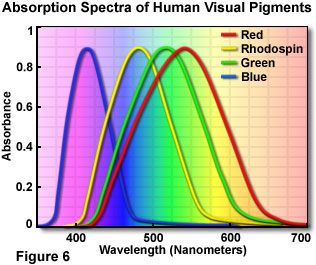
- If light is made up of particles called photons and different wavelengths are associated with different photons of different energies then how do we make out the difference? With light, the way we distinguish them is by the sense of colour. We associate different colours with different wavelengths. The nature of perception will be dealt with later but it would be good to look at some aspects of it now. Perception is dependent on the physiology of the eye and our eye is sensitive to light, its absence and the various shades in between. It is also sensitive to three colours. That is to say we have nerve endings in the eye that can measure the intensity of the light - these are known as rods. We also have three other types of nerves- all called cones - that respond maximally to three different wavelengths. The rods respond best to wavelengths in the 500 nm range. Rods have a wider range of response than the cones. The extent of response of the cones will depend on the wavelength. Light which consists mostly of wavelengths around 430 nm it will be seen as blue. If it is around the 540 nm range it would be seen as green and if it is around 600 nm it would be seen as red. If the wavelength is somewhere between 540 and 600 nm then both the specialised cones will be excited to a limited extent and this will produce a sense of yellow. Interestingly, if we were to shine light of wave lengths 540 & 600 nm we would still produce a sense of yellow as the two cones which are sensitive to these wavelengths are excited. The fact that more than one type of cone is excited implies that colour vision is additive and red, green and blue are called the Additive Primary Colours.


As you can see in the adjacent figure when all three additive colours appear together we get white. Blue and Green together give the sense of Cyan, Blue and Red a sense of Magenta and Green and Red gives Yellow. What happens if we remove Red from white light? We get Cyan – the combination of Blue and Green. Similarly, Yellow and Magenta are produced by removing Blue and Green respectively. That is why these three colours are called Subtractive Primary colours – they are produced by removing one colour from white light. In the figure above you can see how the additive primary colour is produced by mixing different subtractive primary colours – only the common colour is visible when two subtractive colours are mixed – green is produced when cyan and yellow are mixed etc. When you mix all three the result is Black. This is true even with light on a computer screen as you will see in the interactive demo available in the attached folders.

This by itself does not explain all the colours that we see. For example colours like brown do not exist in the combination of the primary colours. For this we need to add additional dimensions. Every colour that we see is actually a combination of a number of wavelengths. The rim of the disk in the adjoining figure shows the range for the primary colour combination. This is what we know as ‘Hue’. The ratio of the dominant or primary wavelength to the other wavelengths defines the parameter ‘saturation’ which moves you radially along the disk from the centre for maximum saturation at the rim for each of the colours in the combination. The last parameter is the ‘brightness’ – the intensity or energy associated with different wavelengths - and is shown as the trunk of the tree in the accompanying diagram. You can see that by varying the three parameters we can get the colour that we want – including colours like brown and grey.
All this discussion is in relation to mixing of
light. When we mix pigments the process is very different. The
primary pigment colours are red, yellow and blue. In the case of
pigments only specific wave lengths of the white light that is
incident on the pigment are reflected. So red pigment will
predominantly reflect red light, yellow light will predominantly
reflect yellow and so on. When we mix blue and yellow pigment we get
green, red and yellow gives us orange, red and blue gives us purple
and so on.
Key vocabulary
- Light – the kind of energy that allows us to see
- Electro magnetic radiation - The way light energy travels
- Photon – The packets of energy that light consists of
- Wavelength – a property associated with different colours. We can try and explain this in greater depth when we work on the sound module.
- Additive Primary Colours – the colours of light to which our eyes are sensitive and which together combine to form white light.
- Subtractive Primary Colours – the colours produced when one of the additive primary colours is removed from white light.
- Hue, Saturation and Intensity – The three parameters that allows us to see all the different colours including colours that are not part of the VIBGYOR spectrum.
Additional web resources
For this section also see the following :
Olympus Microscopy Resource Center Physics of
Light and Color
www.olympusmicro.com/primer/lightandcolor/primarycolorsintro.html
www.olympusmicro.com/primer/java/primarycolors/additiveprimaries/index.html
www.olympusmicro.com/primer/java/primarycolors/subtractiveprimaries/index.html
These web sites will also allow use of some interactive programs on-line and that will clarify things further.
How we see
- The human vision is a very complex process. Vision is a result of the two eyes working almost simultaneously with large portions of the brain to produce the sensation of vision.
- The first step in the process is the stimulation of the light sensitive receptors in the eye. This information of the image is then converted into electrical signals which are transmitted by the optic nerve to the brain where it undergoes a lot of pre-processing before reaching the visual cortices in the cerebrum. It is at the end of this process that we have a sense of vision.
- We must remember that the eye is actually an extension of the brain and is only one tool in the entire process of vision. The optical parts of the eye, as can be seen in the accompanying figure are:
If the LDD is closer to the eye then we would find that we are unable to see things that are at a distance clearly. (We would also notice, for example, that we need to hold a book closer to our eye in order to be able to read it.) Such a problem is known as Myopia or Short Sight. This is a problem that can affect people of any age and is generally due to the lens not being able to change its focus properly.
If the LDD is farther from the eye – we would
have to keep the book farther away form us – the condition is known
as Long Sight or Hypermetropia. This generally happens with older
people. Occasionally it can happen with young children and is likely
to be because of corneal problems.
If the cornea bulges in an odd way and so distorts
the image that forms on the retina – here the LDD remains the same
- then the condition is known as Astigmatism. All these problems can
be corrected by using spectacles with appropriate kind of lenses.
Nowadays you can also correct this condition by changing the shape of
the cornea.
Key Vocabulary
- Cornea – the front bulging part of the eye
- Pupil – The part of the eye which allows light to enter the eye. This is in the middle of the Iris.
- Iris – The different coloured portion of the eyeball
- Lens – the part of the eye that causes a clear image to be formed on the Retina
- Retina – The portion of the eye which transmits information to the brain.
- Rods & Cones – Different parts of the retina. Rods are sensitive to brightness and are used to distinguish between light and dark. There are three kinds of cones that are sensitive to the three primary colours – red, green and blue.
- Optic Nerve – The nerve bundle that connects the eye to the brain.
Colour Blindness – The problem with the eye that does not allow human beings to not see different colours properly. - Myopia – Short sightedness. The problem which makes it difficult to see distant objects clearly.
- Hypermetropia – Long sightedness – The problem that makes it difficult to see objects clearly when they are close to the eye.
- Cataract – The clouding of the lens in the eye that causes blurred vision.
Additional Resources
For this section also see the following:
www.olympusmicro.com/primer/lightandcolor/humanvisionintro.htm
Physical aspects of light
Essentially we will see how light travels through and interacts with various materials.
We saw that we do not actually see things – we
only see the light reflected of things. We had also noted that only
part of the radiation gets reflected and some of it gets absorbed and
the colours that we see are the colours of the light that is
reflected. We summarised the nature of light – that it is a form of
energy and interacts as a particle and travels as a wave; that all
electromagnetic radiation comes as unique packets of energy known as
photons and different kinds of photons have different amount of
energy associated with them. The different amounts of energy are what
cause different electromagnetic radiation to interact differently and
this is what gives us the idea of colour.
We tried to understand how we see – that vision
is lot more than light falling on the retina. There is a lot of
interpretation of the information that is received at the retina that
takes place in the brain. We also looked at the possible ways in
which vision can be distorted.
In this section we shall look at how travels
through different media and how this movement from one media to
another can change the direction in which light can move. We will see
how fast light travels in different media and how this affects its
movement. This will give us an understanding of how light is
reflected, refracted and absorbed and how lenses work etc.
- Just like any object with energy, photons can be absorbed, bounced off or pass through the object. It is useful to think of matter as analogous to a large netted material. If the netting is fine then all objects thrown at it will bounce of it. If, however, the spaces within the netting is a large number of smaller objects can pass through it. Larger the spaces more and larger objects can pass through. When objects go through netting they are deflected by the netting and also tend to move slower losing their energy. Some times the object will get stuck in the netting.
Of course the analogy is not exact and we should be careful using this. Photons are packets of energy and are not objects with mass and kinetic energy and the behaviour is not identical.
All materials absorb, reflect and refract light to
different extent. Different materials absorb different amounts from
different areas of the electromagnetic spectrum. Light which consists
of relatively low energy photons will be reflected by most objects
whereas the high energy photons of X rays will pass through most
objects without any change.
- Reflection and absorption involves a photon interaction with the electrons of the atoms that constitute the material. This interaction would result in excitation of the electrons in the atoms that constitute the matter. The excited electrons release photons when they move into lower energy shells. If the released photon is identical to the incoming photon then we have a reflection process at work. When the photon is different – typically a lower energy photon(s) we say that the light is absorbed. This is what happens, for example with black material that absorbs a higher energy light photon and gives out lower energy infra-red photons. Obviously no material can reflect all light or absorb all light photons. Depending on the nature of the released photons we say an object is a good reflector or a good absorber.
- The process of refraction is slightly more complicated. If we go back to the analogy of a fast moving object moving through a net material we know that the speed of the moving object will slow down. In a similar way the photon moves at different speed in different materials. The maximum speed electromagnetic radiation (actually anything – not just electromagnetic radiation) can achieve is 300,000 Kms per second. This speed is achieved only in vacuum and the speed is much slower everywhere else.
- Obviously such movement is possible only when the photon is not absorbed. This process of slowing down also results in a change in direction if the ray strikes the surface obliquely.

- One way of thinking of how this works is to think of an oblique row of photons striking a surface – as in the figure on the side where each line is an image of the same row of photons but at different times. That is to say, each successive line shows the same row of photons but at a later time. Keep in mind that our sense of image comes from the effect of all the light photons that strike our eye at a particular time.
- What we see is that the photons that have entered the second denser medium 2 have got slowed down and travel lesser distance than the photons that are still in medium 1. So the snapshot of the line of photons will bend at the interface – photons that have entered the medium 2 travel at a slower rate than the photons in medium 1 and the line of photons that represent all the photons travelling together at a particular point of time will also bend. When the entire row of photons has entered the second medium entire the line of photons will appear to be bent. This is why refraction takes place – photons travel at different speed in different medium.
- We can now also see why if the light is perpendicular to the interface no refraction will take place. The row of photons will move slower in the denser medium but will not undergo any bending. We must remember that all the refraction takes place at the interface and not inside the medium. We must remember all mediums reflect, absorb and refract radiation to different extents.
- In the case of reflection it is useful to remember that photons possess momentum and the law of conservation of momentum is applicable. So it is natural to expect that a normal ray will retrace its path and an oblique ray will be mirrored on the normal – that is the angle that the reflected ray or photon makes to normal is the same as the angle that the incident ray or photon makes to the normal. This would be true when we bounce a ball of a smooth flat wall for the same reason. What happens if the wall is curved? The reflection law will remain true but the normal will be different at every point and therefore the direction of the ball, and the photon, will be different at every point and how the photons will bounce will depend upon the normal at that point. This explains why curved mirrors reflect light differently from a plane mirror. It also explains why concave mirrors are converging mirrors and convex mirrors are diverging.
- In the case of refraction, the extent of refraction will depend on the extent of obliqueness and the nature of the two mediums. That is to say the amount of bending will depend on the velocities of light in the two mediums (we normally talk of refractive indices and these are nothing but the ratio of the velocity of light in the two mediums with respect to the velocity of light in vacuum) and the extent of obliqueness – that is the angle of incidence. We can derive the relationship Sin i/ Sin r = c1/c2 ,where i is the angle of incidence, r is the angle of refraction and c1 & c2 are the velocities of light in medium 1 and 2 respectively using basic trigonometry.
- Here too i is the angle made to the normal and if the incident surface is not a plane then the refraction will vary depending on the nature of the curvature of the surface. So convex lenses converge light and concave lenses diverge light.
It should be noted that when light moves from an optically denser medium to an optically lighter medium light bends away from the normal r > i and i is < r when light moves from a rarer to a denser medium.
We come to a limiting situation
when light moves from a denser to a rarer medium – the incident
angle is increased to the extent that the refracted light is parallel
to the interface. For i greater
then this limiting angle, light cannot escape from the denser medium
into the rare medium! This process is call total internal reflection.
- The ability to change the direction of light by reflection or refraction is very useful and we have a number of devices that use this principle. We can use this to see around corners or over walls – periscopes; we can use convex mirrors so that we can see a large area by making the image smaller – shaving mirrors, rear view mirrors in cars and bikes; we can use plane mirrors to accurately reflect without distortion images of ourselves; we can use large concave mirrors to collect light from a large area and use it to create a bright small image that we can subsequently magnify – this allows us to collect as much light as is possible from far off objects and hence see the objects more clearly – this is what we do in optical telescopes; we can use concave mirrors lenses to collect and focus a large amount of light into a small area – used in some forms of solar heating; we can obtain larger images of small objects by using curved lenses – microscopes; we use the property of total internal reflection for sending data and voice through optic fibre cable where the information is sent as light through thin fibre where the light is continually totally internally reflected; we can apply corrective lenses to our eyes to make our vision better – the list can go on and on.
- We can reconcile the wave model and ray model of light by imagining the ray to be a line normal to the wavefront. Understanding this concept and using Huygens' principle, laws of reflection and refraction can be derived. Huygen's principle states that if the position of a wavefront at an instant is known, the position of the front a later time can be constructed. Related effects of refraction include dispersion and scattering. We saw earlier that white light is made up of constituent colours. We also saw that the extent of refraction depends on the wavelength of the light. Therefore, when white light is passed through a prism, it splits into its constituent colours. This phenomenon is called dispersion.
- Polarization can be thought of and explained in terms of sending a wave through a slit in one direction only. The following tutorial can be used to explain polarization. [[1]]
Key vocabulary
- Absorption – the process by which incident light is not reflected or refracted. Typically the photon is absorbed and a photon of a lower energy is emitted. Sometimes no photon may be emitted.
- Reflection – the process by which a photon striking a surface causes a photon to be emitted
- Refraction – the process by which light passes through different mediums. The light bends at the interface because it travels at different speeds in different materials.
- Concave – A curved surface like the inside of a sphere with an inward bulge at the centre.
- Convex – a curved surface like the outside of a sphere with an outward bulge in the middle
- Plane Surface – A flat surface
- Lens – An object made of some material whose two surfaces can be concave, convex or planar.
Additional resources
Detailed information about the nature of light can also be found at
www.olympusmicro.com/primer/lightandcolor/mirrorsintro.html
www.olympusmicro.com/primer/java/prism/index.html
www.olympusmicro.com/primer/lightandcolor/lenseshome.html
www.physicsclassroom.com/Class/light/u12l2c.cfm
These web site will also allow use of some interactive programs
on-line and that will clarify things further.
Quantitative study and experimentation
Based on all the above discussions, students would have developed an appreciation of the nature of light and what are its properties. Through a mix of detailed drawings, numerical problems and experimentation, students can develop a more thorough understanding of how light behaves. From here, the student will also be introduced to more advanced and current topics like digital photography, LASER, etc.
At this stage students move from very
hands-on to abstraction. Students are formally introduced to the
process of experimentation, recording, representation and
documentation. At this point, through a mix of theoretical
discussions, formal experimentation, students should develop an
understanding of the following ideas.
Key Vocabulary
At this point, the focus could be on learning the following theoretical concepts. These are the knowledge outcomes that the students should have.
Reflection
- What happens when light traveling through a medium and is incident on any other surface?
- Can you distinguish between regular and irregular reflection? Which helps us see better? Why?
- What are the terms associated with reflection? Can you define them? (Mirror, Incident Ray, Point of Incidence, Reflected Ray, Normal, Angle/ Glance Angle of Incidence, Angle / Glance Angle of reflection
- What are the laws of reflection?
- What are the features of an image formed by a plane mirror? (real or virtual, distance from mirror, orientation, effect of rotation of incident ray, height of mirror reqd. for a full image). Can you construct an image of an object formed using a plane mirror?
- Formation of images in two mirrors – parallel and perpendicular and at any other angle. Where is this property used? Can you draw a simple ray diagram for a periscope? Where is a plane mirror used?
- Can you visualize a spherical mirror? (Think of it as a plane mirror bent inwards or pushed outwards) What are the terms associated with a spherical mirror? Can you define them? (Spherical mirror, concave/ convex mirror, pole, centre of curvature, principal axis, linear aperture, principal focus - F, radius, focal length –f
- Can you draw ray diagrams showing converging and diverging mirror? Can you derive the relation R = 2f
- Constructing images from spherical mirrors.
Refraction of Light
- When does light travel in straight lines?
- What happens when a ray of light travels from one medium to another?
(it deviates, the phenomenon of refraction, what happens to frequency, what happens to wavelength)
Definitions associated with refraction (incident
ray, point of incidence, normal, angle of incidence, refracted ray,
angle of refraction)
- What happens when a ray of light travels from denser to rarer medium and rarer to denser medium? Does the light suffer refraction when it hits at right angles?
- State the laws of refraction. Can you geometrically arrive at the refractive index? How is refractive index related to the speed of light?
- Can you draw a diagram and show (i) lateral displacement (ii) reversibility of light
- Can you describe the applications of refraction? (real, apparent depth, position of stars, multiple images from a glass slab, etc.)
- Numerical problems around refractive index using when speed of light, real-apparent depth, sin i/ sin r.
- What do you mean by total internal reflection? Can you draw a ray diagram to describe total internal reflection? What conditions have to be satisfied for this to occur? How is it related to the refractive index?
- Effects of total internal reflection? How does it differ from reflection?
- Can you draw diagrams to show deviation through 90, 180 in prisms? Can you also draw diagrams showing how light passes through no-deviation prisms?
- Draw and label parts of a prism (refracting angle, refracting edge, angle of prism). Show with the help of a diagram, angle of deviation? What does it depend on?
- What is a lens? Definitions associated with a lens (centre of curvature, radius of curvature, principal axis, optical centre, principal foci). When will the two foci be equidistant from the optical centre (medium on both the sides has to be the same)
- Can you explain the converging and diverging actions of convex and concave lens? Can you draw the contrast with respect to mirrors?
- Be able to construct an object-image table for convex and concave lenses. {| border="1" |- | Object position | Image position | Size | Type |}
- Be familiar with the technique of constructing a ray diagram.
- What do you mean by magnification? Can it be greater than 1? Less than 1? Equal to 1? Under what conditions? With the help of diagrams, explain magnification in a simple microscope and in a magnifying glass.
- Draw a diagram to show how focal length of a convex can be determined using the plane mirror method and the distant object method.
- What are electromagnetic waves? What is white light composed of? How does light cause the sensation of seeing? Are white and black colors?
- Why do we have so many shades of colors? Which is the color with the least wavelength?
- Can you define spectrum, dispersion, impure spectrum, pure spectrum, monochromatic and polychromatic light?
- With a diagram, show dispersion of while light in an equilateral prism. Which color refracts the most?
- Describe the various kinds of waves in the electromagnetic spectrum with the approx. wavelengths). Can you describe the relationship between energy associated with a wave and its wavelength?
- Be able to describe qualitatively how UV and IR waves came to be discovered.
- What is invisible spectrum? What are the sources, properties and uses of ultraviolet and infrared radiations.
- Briefly describe the eight major bands of the electromagnetic spectrum and where they are used.
- Why is the sky blue?
Additional resources
[[2]]
[[3]]
[[4]]
[[5]]
[[6]]
[[7]]
[[8]]
Activities
What is light?
Objective:
To understand the nature of light
Procedure:
Watch the videos listed below. The accent is different; so the teachers can watch it before and then share with the class.
- What is light 1 through 3.
- Bill Nye the Science Guy – Light and Colour 1_3 through 3_3
Discussion/ questions:
- Light is a form of energy.
- It travels as radiation. It does not require a medium to travel.
- It is made up of small packets of energy called photons.
- Different types of photon have different amount of energy associated with them.
- The different types of photons are seen by us as different colours.
- There are some kinds of photons that we cannot see – for example heat radiation, X rays, infra-red and ultra-violet rays. We say that light travels as a wave and different coloured lights have different wave-length associated with them.
How to mix pigments
Objective:
To observe and understand the constituents of light.
Procedure:
We can use drops of poster colour or take small quantities of any water soluble paint. Be sure to use Red, Blue and Yellow – the primary colours for mixing pigments.
Children must write their observation clearly in
the following format:
Evaluation
How have the
children recorded their observations?
What is their
working method?
How to mix colours?
Objective
To study recombination of colours.
This experiment allows children to try and look at
what happens when they mix coloured light. The second part of the
experiment will use 2 or 3 colour filters with one torch. This will
work because the cellophane filter only enriches the red colour. The
other colours are still there. When we add one more sheet the colour
will be the addition of the other filters. Of course the light will
become dimmer and dimmer as more and more light will get absorbed by
the filters.
Materials:
- Three Torches. Any kind of torch light torch will do. Make sure all of them have beams of the same intensity
- Coloured transparent cellophane Sheets – Colours required Red, Blue and Green.
- Cellotape
Procedure
- Cut small sheets of red, blue and green cellophane sheets. These pieces should be big enough to fold over and still be big enough to cover the torch beam.\
- Wrap each of the coloured sheets over separate torches making sure that the sheet is flat over the transparent glass in the front of the torch.
- Tape it securely from the sides. We should now get torches which give a clear beam of red, green and blue light respectively.
- If we shine the torch on a white paper so that we get a clear circular image of each of the colours.
- Aim of the experiment
- Method
- Observation when
- The red beam and green beam are mixed
- The red and the blue are mixed
- The blue and the green are mixed
- When all three of them fall together
- When we used more than one sheet with the same sheet
- Red and blue sheet together
- Blue and green sheet together
- Green and red sheet together
- All three sheets together
Evaluation
- What are the various forms of energy? Where does all energy come from?
- How are we able to see?
- What is white light? When do we see white and black?
We see them because they reflect light. If they reflect all the incoming white light then we see it as white. If it does not reflect any light but absorbs all of it then we see it as black. If it reflects some colours and absorbs others then we see it as the colour of the light that it reflects. A tomato is red because it absorbs colours other than red and reflects red light. A green leaf is green because it absorbs all light other than green.
Black is Hot! White is Cool!
Objective
At the end of this experiment children should be able to recognize that black objects absorb more radiant energy than white objects. This is a simple experiment that can be done in the classroom or at home. Children should report their findings in a formal way – this is to help them formalise their understanding:
Materials:
One piece of black cloth. A similar sized white cloth. Ideally
the two materials should be the same and texture. It may not be very
critical if they are not.
Cloth pieces of other colours but similar material
and texture.
Procedure
- Leave the two pieces of cloth out in direct sunlight for about 15 minutes.
- At the end of the period feel the clothes.
- Try this with other coloured clothes
Observations must be written in the following format:
- Aim of the experiment
- Method
Evaluation:
Answer the following questions.
- Which seemed warmer the black or the white cloth?
- If you used other coloured clothes
View optical illusion
Objective
To introduce the idea that eye plays a role in what we “see”.
Procedure: View some of the illusions in the folder “Optical illusions classroom.” Not all of them will work on the big screen. Those that do not can be viewed in smaller groups by the children.
How many fingers do we have?
This is really not a full fledged experiment but a
way of introducing the way our eyes can confuse us. This is to be
done in the beginning of the unit.
Materials: None
Procedure
- Ask the children to bring their index fingers together in front of their eyes at a distance of about 5-6 cm from the eyes. They should focus on a distant point in front of them and then move their fingers towards and away each other.
- They should be able to see a finger in the middle that seems to wiggle as they move the finger front and back or up and down!
Discussion/ questions
Discuss why we see things differently from the way
it actually is. How is it that illusions are able to fool us? Why do
we see an extra finger when we know there is no extra finger? The
discussion should help us explain that we do not see only with our
eyes –the eyes are only a part of the things that we need to see.
We see because of our eyes, because of the nerves that connect our
eyes to our brain and the brain itself. The brain makes sense of all
the information that the eyes have given to it. Of course as we see
in the case of the optical illusions the brain can be fooled
sometimes. But most of the time it makes complete sense of what we
see.
The lens shape
Objective
The lens shape is adjustable and this adjustable shape is what causes a sharp image to be formed on the retina – the lens adjusts its shape until a sharp image is formed in the lens. How does the lens adjust itself?
At the end of this experiment children should be
able to recognize that changing the shape of a lens allows different
kinds of images to form. Again this is an experiential experiment –
no formal observations need to be recorded. However they must write
what they did and what they saw in plain English.
Materials:
- One Ziploc bag.
- Water.
- Brightly coloured objects to view through the lens
Procedure
- Fill the Ziploc/plastic bag with water to about 2/3rds its capacity. It should be possible to squeeze it and change its shape without the water spilling out.
- Secure the Ziploc properly.
- Try looking through the Ziploc bag at various objects – including each other!
Evaluation
- What happened when we moved the bag backwards and forwards?
- What happened when we squeeze the bag and change its shape?
Discussion/ questions
Why do we have 2 eyes? They provide the brain with
two different images which are separated by a small distance – get
the children to look at an object first with one eye and then the
other. They will see the image shift slightly – this is because the
angle at which we see with each eye is slightly different. The two
images go to the brain and the brain is able to get a 3D image of the
object because of this. Remind them how we can fool the brain – we
did that on the first day when we grew an extra floating finger
Blind Spot!
Objective
At the end of this experiment children should be able to find out that they have a blind spot – image formed at that point are not visible. No written work for this exercise.
Materials: Blind Spot sheet
Procedure
- Keep the sheet about 20 – 25 cm away from the eyes.
- Close your right eye with your hand.
- Now focus on the circle on the right with your left eye.
- Move your head slightly. At one point you will find that the cross on the left disappears!
- The moment you turn to look at it, it will reappear.
- You can do the same experiment but closing your left eye with the figure below where the circle is on the left and the cross is on the right.
Formation of shadows
Procedure
- View the videos - Hand shadows\A_Magical_Hand_Shadows_Show & Hand shadows\Amazing_Hand_Shadow_show_by_Raymond_Crowe. We can use the light of the projector to make shadows on the screen (if available).
- Discuss how shadows are caused. Shadows are areas where light does not reach. Since we only see reflected light areas where light does not reach appear black – the colour we associate with the absence of reflected light. Also discuss what kinds of objects are there –
Play with mirrors
Objective
To introduce the children to reflection using mirrors.
Procedure
View Arvind Gupta video.
Discussion/ questions
- What is symmetry?
- What can we say about an image formed using a plane mirror?
Appearance of a coin
Objective
To study real and apparent depth.
Procedure and discussions
When you add water to a beaker, the coin appears at some level of water. Lead the discussion to real depth and apparent depth.
Introduce
a pencil
into a beaker and view it from below. We find that we can view only
the portion of the pencil below the water. This is because total
internal reflection takes place at the surface of the water and we
are unable to view the rest of the pencil! This could be a good way
of introducing total internal reflection.
Formation of a real image
Objective
To study the formation of a real image.
Materials:
Cardboard box, screen, candle
Procedure:
Make a pinhole camera with a cardboard box and demonstrate the image formation.
How to draw a ray diagram?
When an image is formed and it can be seen on a
screen, we call this a real images
Evaluation
The children have now moved from various
conceptual understanding to formal study and definitions.
- What is the nature of light?
- When are shadows formed?
- Can you make a pinhole camera and show image formation?
- When do we see white light what does it mean?
- How are other shades of light seen?
- What is the structure of the eye?
- How are eclipses formed?
Standard Lab Experiments
The following standard experiments can be completed for further study on light. The materials and procedure is available in prescribed lab books.
Laws of reflection (plane mirror)
Construction of ray diagrams
Refraction using a glass slab
Refraction using a prism
Calculation of focal length of a convex lens
Auxiliary plane mirror method for determination of focal length
Additional Information
Multiple mirror systems
Besides right angle mirror systems, there is a wealth of other multiple mirror systems that involve two or more mirrors. If two plane mirrors are placed together on one of their edges so as to form a right angle mirror system and then the angle between them is decreased, some interesting observations can be made. One observes that as the angle between the mirrors decreases, the number of images that can be seen increases. In fact as the angle between the mirrors approaches 0 degrees (i.e., the mirrors are parallel to each other), the number of images approaches infinity.

 The generation of two images is not difficult to explain; each of the two
mirrors produces an image due to the single reflection of light off
one of the mirror faces to an observer's eye. The remaining images
are produced as the result of multiple reflections of light off more
than one of the faces. Right angle mirrors will allow a maximum of
two reflections of light from the object. But as the angle decreases,
three, four, and even more reflections can occur.
The generation of two images is not difficult to explain; each of the two
mirrors produces an image due to the single reflection of light off
one of the mirror faces to an observer's eye. The remaining images
are produced as the result of multiple reflections of light off more
than one of the faces. Right angle mirrors will allow a maximum of
two reflections of light from the object. But as the angle decreases,
three, four, and even more reflections can occur.
Determining the image locations
for such multiple mirror systems can become complicated. First
determine the location of the primary images using the principle that
the image distance to the mirror is the same as the object distance to the mirror. Each primary image forms a secondary image as a
result of a double reflection. By extending one of the mirror lines,
a primary image can be reflected (a geometry term, not a
physics term) across the second mirror line to form a secondary image
- an image of an image. As an example, consider the diagram
below for an object placed between two plane mirrors that make a
60-degree angle. Images I1 and I2 are primary
images formed by the two plane mirrors. Image I3 was found
by reflecting image I2 across the extension of
the top mirror. And image I4 was found by reflecting
the image I1 across the side mirror. The process can be
repeated to determine the location of an image of an image of an
image.

Ray diagrams for these multiple
mirror systems are drawn much like they were for right angle mirror systems. Once you have located the images, begin by
drawing a line of sight towards the image; this would be the
reflected ray that ultimately travels to your eye. For a secondary
image, this reflected ray is associated with an incident ray that had
reflected off the other face of the mirror. The law of reflection can
be used to determine the direction it was traveling as it was
incident upon this face of the mirror. Repeat this process to
determine the point of reflections on each face, tracing the path of
light back to its origin - the object itself. A completed ray diagram
for a secondary image on a 60-degree mirror system is shown below.

Polarization pictures


The passage of unpolarized light through the atmosphere is not the only means by which light becomes polarized. Light can also become partially polarized when it reflects off a non-metallic surface. For instance, light reflecting off a puddle of water (or any body of water - large or small) will become partly polarized. The result is that there will be a glare produced when taking a picture of the body of water. The glare often prevents the viewing of objects below the water - a particularly troublesome feature for fisherman who wish to see fish below the water.
The surroundings are reflected in a puddle of water. The photograph is taken with a polarizing filter, set so as to allow the maximum amount of light through.
In this photo, the reflected glare that was seen on the water's surface (previous photo) has been removed by the use of a Polaroid filter. It is much easier to see the sidewalk below the water surface.
Polaroid filters are made of long-chain polymer molecules. They're made such that the long-chains are stretched mostly in one direction. These molecules absorb light that is vibrating in a plane that runs parallel to the molecules. So when a Polaroid filter is turned, the orientation of the molecules is also turned. As the molecules are aligned with the plane of vibration of the polarized light, the polarized light becomes blocked. As mentioned in the earlier photo, the plane of polarization caused by reflection off a non-metallic surface is parallel to the surface, Because the glare seen in the above photo is caused by the reflection off a horizontal surface, the reflected glare can be removed when the molecules are oriented horizontally.
Electromagnetic spectrum

When a low pressure gas such as hydrogen is heated or somehow energized,
it gives off light. When analyzed using a diffraction grating (or
similar apparatus), the light that is emitted is observed to have
certain discrete wavelengths. Rather than consisting of a continuous
spectrum of wavelengths, the emitted light is characterized by only
certain wavelengths - for example, a blue wavelength and a red
wavelength. The photo at the right depicts a portion of the line
spectrum of hydrogen gas.
Scientists have determined that
these wavelengths of light (and their associated energy) is related
to electrons in the atom changing from a high energy to a lower
energy state. The difference in energy of the electron is equal to
the energy of the emitted light.
Interference
Interference phenomena are most often observed on the surface of water with water waves. A disturbance of the water at any location will produce waves that travel outward from the disturbance's location in all directions at the same speed.

Because of this trait of traveling outward from the disturbance location at a uniform speed, the ripples that are formed have a circular shape. These circular waves, as they are often called, can meet up with each other as they travel across the water. The meeting up of two waves at a given location is called interference. Wherever they meet, the amount that the water is displaced at that location is the combined effect of the amount of displacement of each individual wave upon the water.


This photo shows the use of a ripple tank to study two point source
interference pattern. The water in the tank is disturbed at two
locations; the circular ripples that are formed interfere to form a
pattern. Destructive interference results when a crest from one
source meets up with a trough from the other source. When this
occurs, a point of no desplacement is present; these points
are called nodes. In a two point source interference pattern,
all the nodes lie along lines that emanate outward from between the
sources. These lines are called nodal lines.
Constructive
interference occurs when two crests (or two troughs) from the
different sources meet up. The locations where these occur are called
antinodes. Similar to the case of nodes, all the antinodes lie
along lines. These lines are called antinodal lines. The nodal
and antinodal lines of the interference pattern are marked with
dashed lines in the photo.
The wavelength of light can be measured by knowing
the distance between the sources and the distance between adjacent
antinodal lines at any given distance from the sources. Thomas
Young's experiment involved placing a pinhole in a window shutter to
allow a narrow beam of light to pass through. He then split the beam
into two paths by inserting a narrow card edgewise into the beam.
These two light paths were projected onto an observation screen where
the interference pattern was observed. Bright spots from constructive
interference and dark spots from destructive interference were
observed on the screen.